How to Use This Companion
This guide is a companion to the Lesson 17 — Avtron Load Banks video. Use it to follow along during the lesson, to reinforce the major components and their functions, and to locate troubleshooting information quickly afterward.
Watch for these callouts as you read:
| Callout | What it marks |
|---|---|
| Key Point | An important concept, operational relationship, or commonly misunderstood detail |
| Concept Summary | A short recap that ties a section together |
| Figure Summary | What a schematic shows and what to focus on |
| Troubleshooting Tip | Practical guidance for diagnosing a fault |
| Caution | A safety or equipment-protection note |
Lesson Overview
This lesson covers three Avtron load bank configurations used at FAA facilities:
- Radiator Mounted Manual Load Bank — non-shed, operates on commercial power
- Radiator Mounted Automatic Load Bank — load shed, operates on emergency power
- Remote Automatic Load Bank — outdoor automatic load shed with blower system
Each type builds on the previous. The manual load bank establishes the core circuit logic. The automatic load bank adds load shed control. The remote load bank adds airflow proving and environmental protection.
Required materials: Schematic book, ASCO 962 operator manual, ASCO 434 operator manual
Lesson objective: Given an Avtron load bank schematic, identify components, describe their functions, and describe system operation in accordance with applicable documentation.
Why Load Banks Are Used
Load banks allow testing of emergency generators under simulated load with minimal impact to facility operations.
Periodic load testing is used to verify that engine generators can sustain rated load and support facility operations during an emergency power event.
| Condition | Standard Practice |
|---|---|
| Scheduled maintenance | Load test performed for mobile and standby emergency generators |
| After non-routine maintenance | Load test performed on NAS power systems |
What resistive load banks do:
- Convert electrical energy to heat through resistive elements
- Apply a controlled load directly to the generator output
- Allow the generator to be tested at operating load without loading the facility
- Verify that the standby power system is ready to support facility operations
Typical load shed operating target: 50–80% of rated generator capacity
Operating below 50% risks wet-stacking in diesel engines. Operating above 80% risks overload. All three load bank types are designed to keep the generator within this range during testing.
Note: Specific FAA load-testing requirements and acceptable test loading methods are defined by current maintenance guidance and may vary by equipment type and testing objective.
Load Bank Types Comparison
| Feature | Manual | Automatic | Remote Automatic |
|---|---|---|---|
| Location | On generator radiator | On generator radiator | Outdoors, remote from engine |
| ATS source | Commercial / normal | Emergency | Emergency |
| ATS feature | 14A | 14B | 14B |
| ATS contacts | TS12, TS13 | TS10, TS11 | TS10, TS11 |
| Load control | Technician (manual) | Automatic (load shed assembly) | Automatic (load shed assembly) |
| K99 required | Yes | Yes | Yes |
| CT1 | No | Yes | Yes |
| Load shed assembly | No | Yes | Yes |
| K100 / K101 | No | Yes (FAA mod) | Yes (FAA mod) |
| Blower | No (uses radiator airflow) | No (uses radiator airflow) | Yes (208V AC) |
| S61 airflow switch | No | No | Yes (900 CFM) |
| S62 / HR1 | No | No | Yes (cold weather) |
| S60 | Yes (350°F/310°F) | Yes (350°F/310°F) | Yes (350°F/310°F) |
| DS21 meaning | Over temp | Over temp | Air fail |
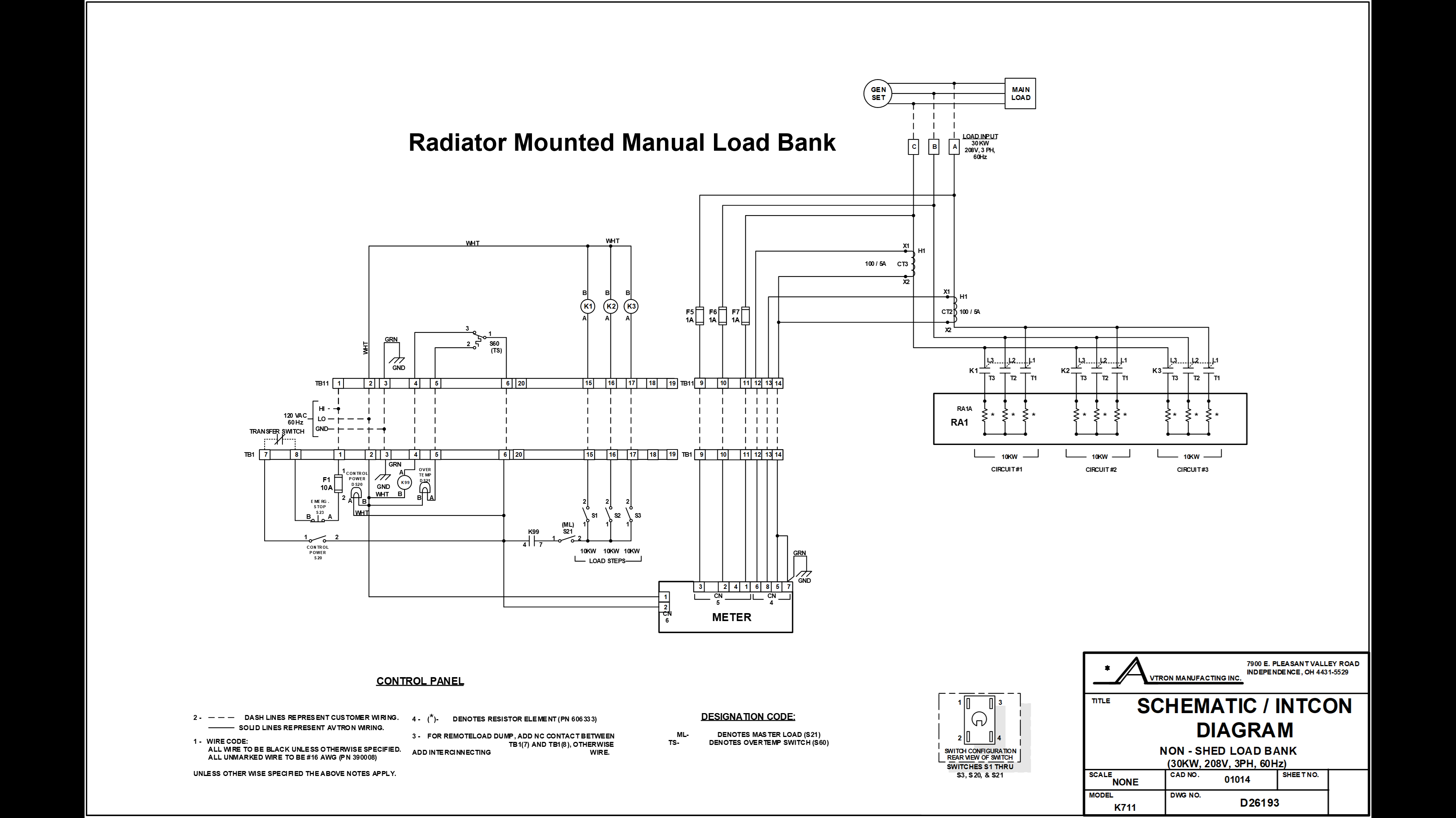
Radiator Mounted Manual Load Bank
What It Is
The manual load bank is a non-shed load bank. "Non-shed" means:
- It has no automatic load shedding capability
- All load steps are applied manually by the technician
- It is disabled by design during emergency power operation
It operates only while the ATS is on commercial power. When the ATS transfers to emergency, control power is removed and the load bank shuts down automatically.
Control Panel Components
| Designation | Function |
|---|---|
| TB1 | Main terminal board — all control panel I/O |
| F1 | 10A protective fuse — panel overcurrent protection |
| S23 | Emergency stop switch (normally closed) — removes all 120V AC from panel when opened |
| S20 | Control power switch (on/off) |
| DS20 | Control power LED — lit when 120V AC is active in panel |
| K99 | Gatekeeper relay — must energize before any load can be applied |
| K99-4 / K99-7 | Normally open contacts of K99 — close when K99 energizes |
| S21 | Master load switch — enables individual load step switches |
| S1 / S2 / S3 | Individual load step switches (10 kW each, 30 kW total) |
| DS21 | Over temperature LED — illuminates when S60 trips |
Load Bank Components
| Designation | Function |
|---|---|
| TB11 | Main terminal board — load bank I/O |
| RA1 | Resistive heating elements — the actual load (3-phase, 208V) |
| K1 / K2 / K3 | Load step coils — normally open contacts close to apply RA1 circuits |
| CT2 / CT3 | Current transformers (optional) — for panel meter only |
| F5 / F6 / F7 | Meter protection fuses (optional) |
| S60 | Over temperature switch — removes K99 control power at 350°F |
How Control Power Flows — Manual Load Bank
Control power must pass through every item in this path before K99 can energize:
120V AC source
    → TB1-1
    → F1 (10A fuse)
    → S23 (emergency stop, normally closed)
    → TB1-8 (exits control panel)
    → TS12 / TS13 (ATS feature 14A — must be on commercial)
    → TB1-7 (returns to control panel)
    → S20 (control power switch, closed)
    → TB1-6 (exits to load bank)
    → TB11-6 (enters load bank)
    → S60 contact 1-to-3 (normal, not over temp)
    → TB11-4 (exits load bank)
    → TB1-4 (returns to control panel)
    → K99 coil → K99 ENERGIZES
When K99 energizes: K99-4 and K99-7 close → DS20 illuminates → load bank ready.
Applying Load — Procedure
- Close S20 (control power switch) → DS20 illuminates, K99 energizes
- Close S21 (master load switch)
- Apply load steps one at a time
- Target: 50–80% of rated generator load
- For the 30 kW schematic: apply any two steps (20 kW) to reach target range
Valid two-step combinations: S1+S2 | S1+S3 | S2+S3
Shutdown Conditions
The manual load bank stops operating when any of the following occur:
| Condition | What happens electrically |
|---|---|
| Load step switches opened (S1/S2/S3) | Load removed from that step |
| Master load switch opened (S21) | All load steps removed |
| Emergency stop opened (S23) | All 120V AC removed from panel |
| Control power switch opened (S20) | K99 de-energizes |
| Loss of commercial power | TS12/TS13 open |
| ATS transfers to emergency | TS12/TS13 open |
| Over temperature condition | S60 trips, K99 de-energizes |
Over Temperature Protection — S60
S60 is the most important safety device in the load bank.
| State | Temperature | Contact position | Effect |
|---|---|---|---|
| Normal | Below 350°F | Contact 1 → Contact 3 | K99 control path complete |
| Trip | 350°F or above | Contact 1 → Contact 2 | K99 coil loses power; DS21 illuminates; load bank de-energizes |
| Reset | 310°F or below | Returns to 1 → 3 | Load bank operation may resume |
When S60 trips:
- K99 de-energizes
- DS21 (over temp LED) illuminates in the control panel
- Load bank is de-energized and loses all load
- Engine continues running
- Technician loses load bank control until S60 resets
Troubleshooting — Manual Load Bank
| Symptom | Check |
|---|---|
| DS20 off after closing S20 | F1 blown? S23 open? ATS on commercial? TS12/TS13 closed? |
| DS20 on, no load applies | S21 closed? K99-4/K99-7 contacts closing? S60 not tripped (check DS21)? |
| Load bank shuts down during test | DS21 lit (over temp)? ATS transferred to emergency? S20/S23 position? |
| DS21 illuminated | S60 has tripped at 350°F. Do not operate. Allow cool-down below 310°F |
| Specific load step does not apply | K1/K2/K3 coil continuity. TB11 wiring at that step terminal |
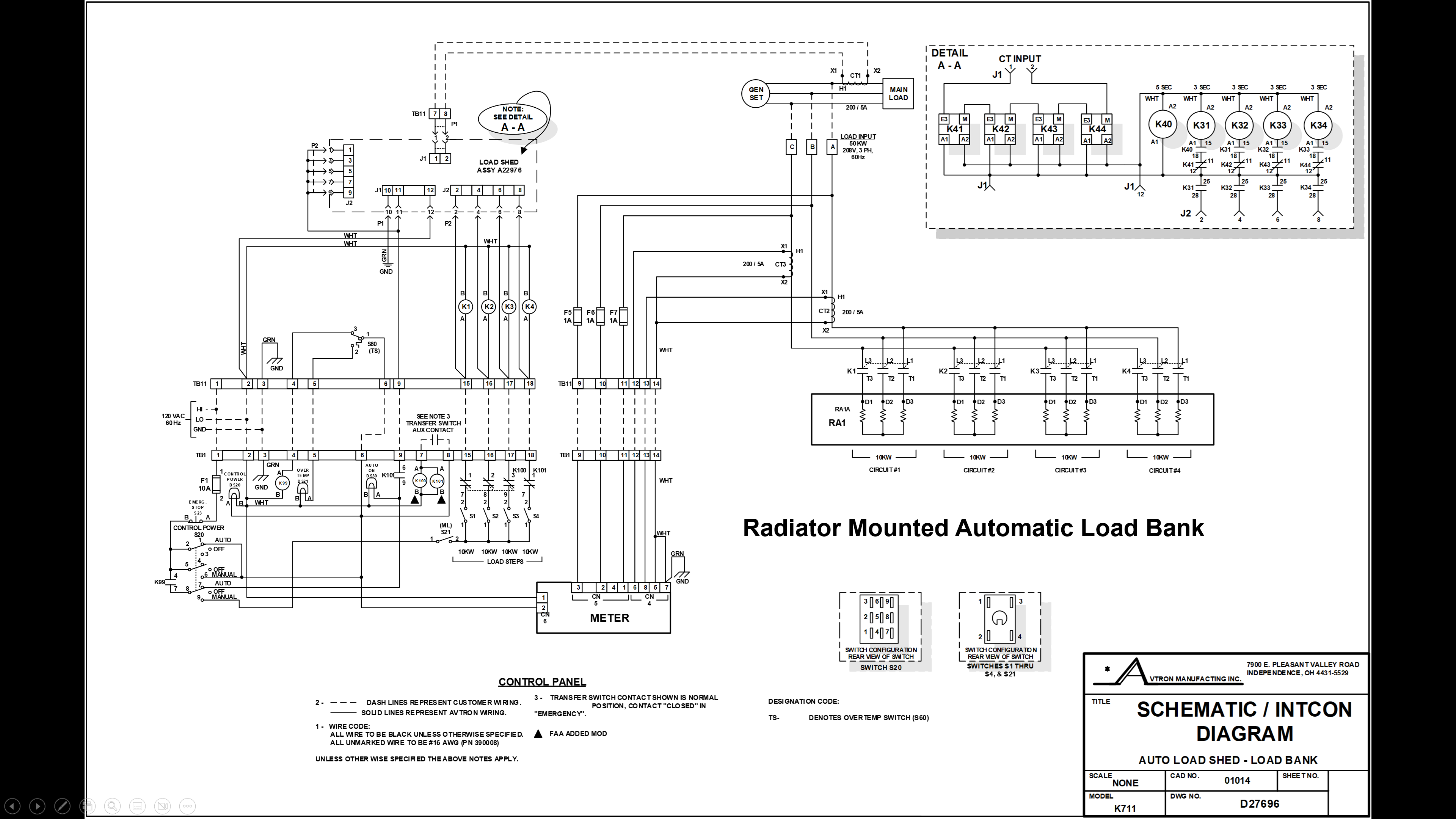
Radiator Mounted Automatic Load Bank
What It Is
The automatic load bank is a load shed system. It:
- Operates only while the ATS is on emergency power
- Automatically adds load bank steps when facility load decreases
- Automatically removes load bank steps when facility load increases
- Maintains the generator in the 50–80% load range without technician intervention
FAA application: Used on Kohler generator sets that do not have an Electronic Control Module (ECM), including many first-generation Kohlers.
Feature 14B and ATS Contacts
| Item | Detail |
|---|---|
| Feature 14B | ASCO ATS auxiliary contact feature for emergency source |
| TS10 / TS11 | Close when ATS is on emergency — enable automatic load shed |
| Schematic Note 3 | All ATS contacts shown in normal (commercial) position. TS10/TS11 are shown open — they close on emergency transfer |
| FAA triangle symbol | Marks K100 and K101 as FAA-required modifications |
Control Panel Changes
The automatic load bank shares most control panel components with the manual version. Key changes:
| Component | Change |
|---|---|
| S20 | Three-position switch: Auto / Off / Manual (was on/off) |
| DS30 | New LED — Auto On indicator |
| K100 | New FAA modification relay |
| K101 | New FAA modification relay |
K100 and K101 — The FAA Modification
When the ATS transfers to emergency, TS10/TS11 close and energize both K100 and K101.
K100:
- Opens normally closed contacts in series with S1, S2, and S3
- Prevents the technician from manually adding load steps while the generator is carrying actual emergency facility load
- Protects against manual engine overload
K101:
- Opens normally closed contacts in series with S4 — disables manual step S4
- Closes normally open contacts — routes 120V AC control power through TB1-9 and conduit to TB11-9, enabling the load shed assembly at connector J1
| K100/K101 state | ATS position | Manual steps | Load shed assembly |
|---|---|---|---|
| De-energized | Commercial | Available | Not powered |
| Energized | Emergency | Disabled | Powered through K101 |
CT1 and Load Monitoring
CT1 is the current transformer that provides feedback to the automatic load shed assembly.
- CT1 monitors the generator output current, which reflects the facility load being carried by the generator
- CT1 converts the high current levels to a proportional lower-level signal
- This signal feeds the load shed assembly at connector J1, terminals 1 and 2
- The load shed assembly uses the CT1 signal to determine when to add or remove load steps
Automatic Operation Sequence
- 120V AC enters panel at TB1-1 → F1 → S23 → S20 (Auto position) → DS20 → TB1-6 → TB11-6 → S60 → TB11-4 → TB1-4 → K99 energizes
- ATS transfers to emergency → TS10/TS11 close → K100 and K101 energize
- K100 opens S1/S2/S3 manual paths — manual step control disabled
- K101 N/O contacts close → 120V AC to TB1-9 → TB11-9 → load shed assembly connector J1
- K99-4 and K99-7 close → control voltage to auto on LED and to load shed assembly
- Load shed assembly begins automatic step control based on CT1 feedback
Detail A-A Explained
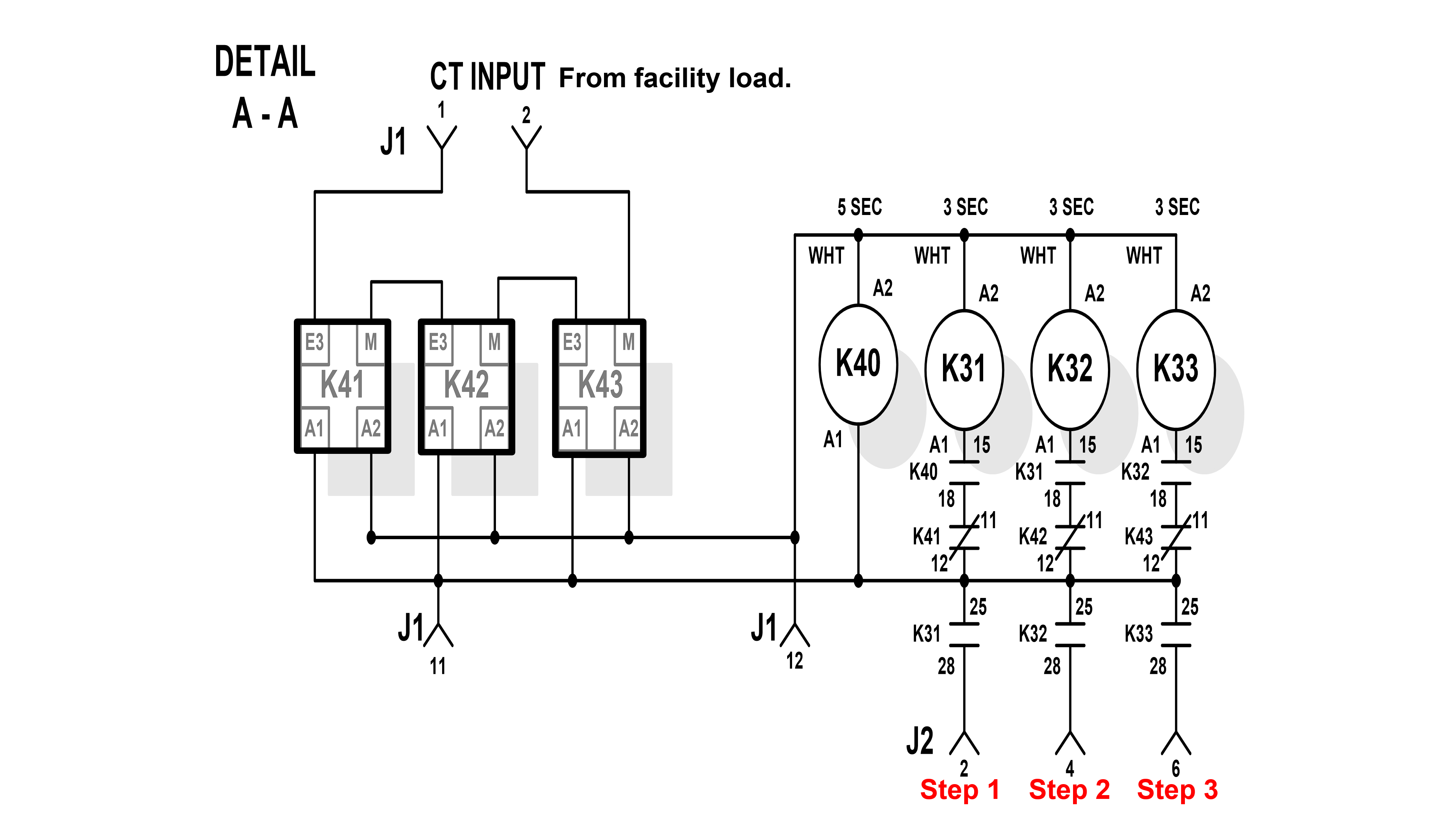
What It Is
Detail A-A is the load shed assembly control circuit. It is shown as an inset on both the radiator-mounted automatic and remote automatic load bank schematics.
Purpose: Keep the generator loaded at 50–80% of rated output by continuously monitoring the facility load carried by the generator and automatically adding or removing load bank steps.
Inputs — Connector J1
| Terminal | Signal | Source |
|---|---|---|
| J1-1 | CT input (+) | CT1 — facility load current signal |
| J1-2 | CT input (–) | CT1 — return |
| J1-11 | 120V AC control voltage | From K101 N/O contacts via TB11-9 |
| J1-12 | Control voltage return / common | Return path |
Outputs — Connector J2
The load shed assembly sends load step commands out through J2:
| Terminal | Step | Destination |
|---|---|---|
| J2-2 | Step 1 | Commands K1 in load bank → applies RA1 circuit 1 |
| J2-4 | Step 2 | Commands K2 in load bank → applies RA1 circuit 2 |
| J2-6 | Step 3 | Commands K3 in load bank → applies RA1 circuit 3 |
Load Step Control Relays — K41, K42, K43
K41, K42, and K43 are the load shed controller's output relays. Each corresponds to one load step.
Important: these relays use inverse logic.
| K4x state | Load step |
|---|---|
| Energized | Load step is removed |
| De-energized | Load step is applied |
K41, K42, K43 relay terminals visible on Detail A-A:
| Terminal | Function |
|---|---|
| A1 / A2 | Coil terminals — load shed controller drives these |
| E3 | Normally closed contact — carries load step path when relay is de-energized |
| M | Normally open contact |
Timing Relays — K40, K31, K32, K33
K40, K31, K32, and K33 are the sequencing relays that gate each load step in a timed chain. They prevent all load steps from being applied simultaneously.
| Relay | Time delay | Energized by | Enables |
|---|---|---|---|
| K40 | 5 seconds | J1-11 (120V AC) | K31 coil path (contact 15) |
| K31 | 3 seconds | K40 contact 15 | K32 coil path (contact 15) + Step 1 output (contact 25/28 → J2-2) |
| K32 | 3 seconds | K31 contact 15 | K33 coil path (contact 15) + Step 2 output (contact 25/28 → J2-4) |
| K33 | 3 seconds | K32 contact 15 | Step 3 output only (contact 25/28 → J2-6) |
Total minimum time from power application to all steps available:
5 + 3 + 3 + 3 = 14 seconds
How Each K3x Relay Works
Each K3x relay has three contact functions:
| Contact | Number | Function |
|---|---|---|
| Chain-forward | 15 | Provides coil path to the next relay in sequence |
| K4x gate | 18 | Gates the corresponding K4x relay coil circuit |
| Step output | 25 → 28 → J2 | Provides the actual load step command to J2 |
For a load step to apply, two conditions must both be true:
- The K3x sequencing relay must be energized (contact 18 closed — gating K4x)
- The K4x relay must be de-energized (E3 contacts in closed position)
Neither condition alone is sufficient.
Load Shed Operating Logic
Example: 100 kW generator. Target = 50–80 kW.
Facility load is in range (50–80 kW):
- CT1 confirms optimal loading
- Load shed controller energizes K41, K42, K43
- K41/K42/K43 E3 contacts open → all load bank steps removed
- Load bank on standby
Facility load falls below 50 kW:
- CT1 signals low load
- K41 de-energizes → K41 E3 contacts close → K31 path gates → J2-2 signals K1 → Step 1 applied
- Still below 50 kW: K42 de-energizes → K32 → J2-4 → K2 → Step 2 applied
- Still below 50 kW: K43 de-energizes → K33 → J2-6 → K3 → Step 3 applied
- Continues until CT1 confirms 50–80% range
Facility load rises above 80 kW:
- K43 energizes → K33 de-energizes → Step 3 removed
- Still above 80 kW: K42 energizes → K32 de-energizes → Step 2 removed
- Still above 80 kW: K41 energizes → K31 de-energizes → Step 1 removed
- Continues until generator returns to range or all steps removed
Load steps are applied in order: 1 → 2 → 3
Load steps are removed in order: 3 → 2 → 1
Remote Automatic Load Bank
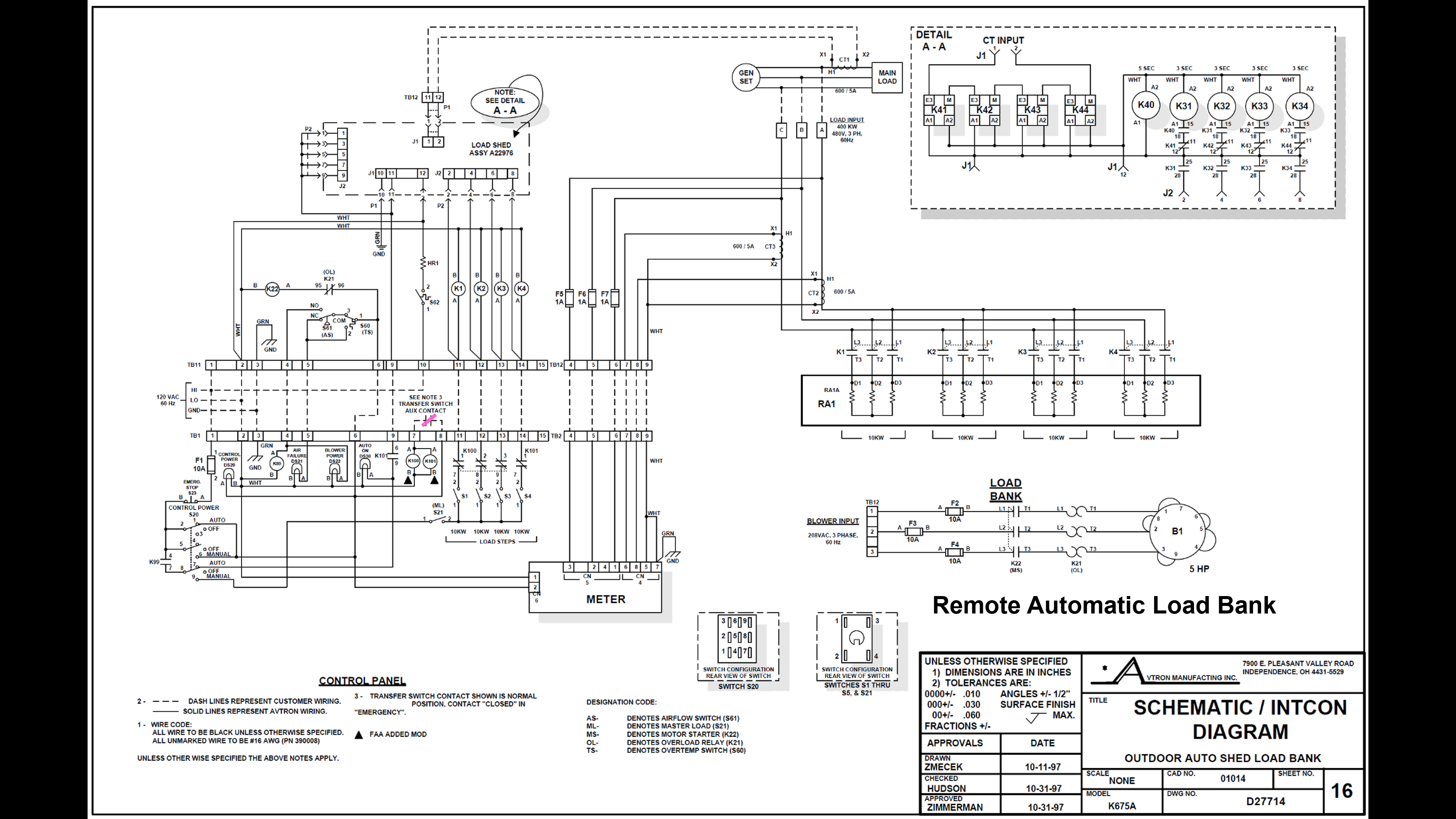
What Is the Same
The remote automatic load bank uses the same core logic as the radiator-mounted automatic load bank:
- 120V AC control power
- K99 gatekeeper relay (required)
- Feature 14B / TS10/TS11 for automatic enable
- K100 and K101 FAA modification relays
- Load shed assembly — Detail A-A circuit
- CT1 for load monitoring
- K40/K31/K32/K33 timing sequence
- K41/K42/K43 load step control
- S60 over temperature protection
What Is Different
The remote load bank is located outside, away from the engine-generator set. Without access to radiator airflow, the unit requires a blower motor to move air through the resistive elements.
Before any load can be applied, the blower must prove it has reached 900 CFM. K99 will not energize until airflow is proven.
New components unique to the remote load bank:
| Designation | Function |
|---|---|
| S61 | Airflow switch — proves 900 CFM before enabling K99 |
| K22 | Blower control relay — N/O contacts supply power to blower when energized |
| K21 | Blower thermal overload relay — bimetal strip trips on prolonged overcurrent |
| DS21 | "Air Fail" LED — lit when airflow is below 900 CFM or K99 is de-energized (note: different meaning than manual/auto load bank DS21) |
| DS22 | "Blower Power" LED — lit when blower is powered |
| S62 | Low temperature switch — closes below 50°F |
| HR1 | Internal heater — cold weather protection |
| TB12 | Blower power terminal board (208V AC at terminals 1, 2, 3) |
| F2 / F3 / F4 | Blower circuit fuses |
| Pitot tube | Airflow velocity sensor — provides signal to S61 |
Blower Circuit
The blower operates on 208V AC supplied through TB12.
| Component | Role |
|---|---|
| K22 coil | Energized by 120V AC control power when system is powered on |
| K22 N/O contacts | Close to supply 208V AC from TB12 through F2/F3/F4 to blower motor |
| K21 N/C contacts | In series with blower motor — normally closed; trips open on prolonged overcurrent |
| F2 / F3 / F4 | Fuse protection for blower motor circuit |
Normal Startup — Airflow Proving Sequence
At initial power-up, two things happen simultaneously:
Path 1 — Air fail indication:
S60 (normal, 1→3) → S61 (normal, below 900 CFM) → exits at TB11-5 → TB1-5 → DS21 Air Fail illuminates
Path 2 — Blower start:
K21 N/C contacts → K22 coil energizes → K22 contacts close → 208V AC through F2/F3/F4 → through K21 motor contacts → blower starts → DS22 Blower Power illuminates
At startup, both DS21 and DS22 are lit simultaneously. This is normal.
| Time | DS21 (Air Fail) | DS22 (Blower Power) | K99 | System state |
|---|---|---|---|---|
| Power applied | ON | ON | De-energized | Normal — blower spinning up |
| Blower at 900 CFM | OFF | ON | Energized | Ready — load shed active |
| K21 trip | ON | OFF | De-energized | Fault — investigate |
Cold Weather Devices
| Condition | Device | Action |
|---|---|---|
| Ambient drops below 50°F | S62 closes | HR1 heater energizes |
| HR1 energized | HR1 heater | Prevents freezing inside the load bank enclosure |
K21 Overload — Cascade Shutdown
If the blower motor draws excessive current for a prolonged period:
K21 bimetal strip heats → K21 contacts open
    → K22 coil de-energizes → K22 contacts open
    → 208V AC removed from blower motor
    → Blower decelerates below 900 CFM
    → S61 switches back to normal position
    → K99 coil loses power → K99 de-energizes
    → Load shed assembly de-powered
    → Load bank inoperable (auto and manual)
Result: DS21 (Air Fail) ON | DS22 (Blower Power) OFF
Engine continues running. Only the load bank is disabled.
Outdoor Maintenance Awareness
Remote load banks are typically located outdoors. Before opening the enclosure:
- Visually inspect the exterior for signs of nesting (mud tubes, insect activity, droppings)
- Use a flashlight to inspect the interior before inserting hands
- Documented enclosure residents: snakes, mice, rabbits, squirrels, bees, wasps, spiders
Pitot tube blockage:
The pitot tube provides the airflow velocity signal to S61. Mud daubers (a species of wasp) are documented to nest inside the pitot tube. A blocked pitot tube prevents S61 from sensing adequate airflow — even when the blower is running at full speed.
Result of blocked pitot tube: DS21 (Air Fail) remains lit, K99 does not energize, load bank inoperable.
Concept Review
Load Bank Types and ATS Conditions
- Manual = commercial power (feature 14A, TS12/TS13)
- Automatic = emergency power (feature 14B, TS10/TS11)
- Remote = emergency power + airflow proven (feature 14B + S61)
K99 — The Gatekeeper
- Required for all three load bank types
- Required in both manual and automatic modes
- Cannot be bypassed
- Failure = load bank inoperable
S60 Temperatures
- Trip: 350°F
- Reset: 310°F
- Contact change: 1→3 (normal) to 1→2 (over temp)
Timing Relay Sequence
- K40: 5 seconds
- K31: 3 seconds
- K32: 3 seconds
- K33: 3 seconds
- Total minimum: 14 seconds
K41/K42/K43 Logic
- Energized = load step removed
- De-energized = load step applied
Seven Manual Shutdown Conditions
- Load step switches opened
- Master load switch (S21) opened
- Emergency stop (S23) opened
- Control power switch (S20) opened
- Loss of commercial power
- ATS transfers to emergency
- Over temperature (S60 trips)
S61 Threshold
- 900 CFM — remote load bank only
- Below 900 CFM: S61 routes to DS21 air fail
- At 900 CFM: S61 switches to K99 coil path
S62 Threshold
- Closes below 50°F — remote load bank only
- Energizes HR1 heater
K100 / K101 Functions
- K100: Energized by TS10/TS11; disables manual steps S1, S2, S3
- K101: Energized by TS10/TS11; disables manual step S4; closes N/O contacts to power load shed assembly
Optimal Generator Load Range
- 50–80% of rated capacity
- Example: 100 kW engine → target 50–80 kW
CT1 Purpose
- Monitors facility load being carried by the generator
- Provides feedback signal to load shed assembly at J1-1 and J1-2
- Enables automatic load step add/remove decisions
Key Terms
| Term | Definition |
|---|---|
| Load bank | Equipment that applies a controlled resistive load to a generator for testing |
| Non-shed | Manual load bank with no automatic load shedding capability |
| Load shed | Automatic function that removes load bank steps when facility demand increases |
| Resistive load | Load that converts electrical energy directly to heat; purely resistive (unity power factor) |
| Feature 14A | ASCO ATS auxiliary contact feature; contacts close on commercial source |
| Feature 14B | ASCO ATS auxiliary contact feature; contacts close on emergency source |
| K99 | Master enable / gatekeeper relay; required for all load bank operation |
| CT1 | Current transformer; monitors facility load carried by generator; feeds load shed assembly |
| Load shed assembly | Control circuit (Detail A-A) that automatically manages load steps based on CT1 feedback |
| Gatekeeper relay | K99; must be energized before any load can be applied |
| S60 | Over temperature switch in the load bank; trips at 350°F, resets at 310°F |
| S61 | Airflow switch in remote load bank; requires 900 CFM before K99 can energize |
| K21 | Blower thermal overload relay (bimetal strip); trips on prolonged overcurrent |
| K22 | Blower control relay; N/O contacts supply power to blower |
| Pitot tube | Airflow velocity sensor providing signal to S61 |
| K40/K31/K32/K33 | Timing relay chain in the load shed assembly; gates load step sequencing |
| K41/K42/K43 | Load shed controller output relays; de-energized = step applied; energized = step removed |
| FAA modification | Circuit change identified by triangle symbol on schematic; K100 and K101 are FAA modifications |
| TB1 / TB11 | Control panel / load bank terminal boards with 1:1 terminal correspondence |
| Wet-stacking | Diesel engine condition caused by prolonged light loading; load testing prevents this |
Lesson Summary
Three load bank types — different sources, same goal:
| Type | When it operates | How load is controlled |
|---|---|---|
| Manual | ATS on commercial | Technician applies steps manually |
| Automatic | ATS on emergency | Load shed assembly responds to CT1 |
| Remote Automatic | ATS on emergency + 900 CFM airflow proven | Load shed assembly responds to CT1 |
K99 is the common thread. Every load bank type, every operating mode, requires K99. If K99 cannot energize, the load bank cannot operate. Understanding what K99 needs — and what can prevent it from energizing — is the foundation of load bank troubleshooting.
The automatic load shed assembly (Detail A-A) adds two relay groups:
- K40/K31/K32/K33 — a 14-second timed sequencing chain that gates step availability
- K41/K42/K43 — the controller's output relays that apply or remove steps based on CT1 feedback
Both relay groups must cooperate for a load step to apply or be removed.
The remote load bank adds one requirement: the blower must prove 900 CFM airflow before K99 can energize. Every additional component in the remote load bank (S61, K21, K22, DS21, DS22, pitot tube) serves this one function.
Periodic load testing and post-maintenance testing of applicable engine generators are standard practice in aviation facility maintenance. Proper maintenance and troubleshooting skills directly support mission-critical facility uptime.
L17 Avtron Load Banks — Lesson Companion
Course: 40167002 Kohler Engine Generator Power Systems
References: Avtron load bank schematics D26193, D27496, D07714; ASCO 962; ASCO 434